0 Introduction M-type grinder is the abbreviation of M1050 type centerless grinding machine. It is a kind of machine tool with higher automation degree. It is mainly used for cutting and grinding of cones with different coning degrees less than 1:20 and various forming rotary parts. Grinding bracket can be used for grinding and processing. Grinding machine control system has been using relay logic control mode, the guide wheel speed adjustment by DC converter control DC motor is not convenient, and low efficiency. 1 M-type grinding machine control process requirements and processes M-type grinding machine is driven by five AC motors, one of which requires stepless speed control. The inverter controls the motor to achieve stepless speed change. The main motor control objects are the lubrication, cooling, grinding wheel, hydraulic and guide wheels. 2 M Type Grinding Machine Electric Control System Ultrasonic Spare Parts,Ultrasonic Horn,Ultrasonic Booster Prosper Industry And Trade Co., Ltd. , http://www.pxweldingmachine.com
In order to solve the shortcomings of the above-mentioned grinding machine control system, it was decided to implement a new design for its electrical control system. Using PLC and variable frequency speed control technology to transform the grinding machine control circuit controlled by traditional relays, changed the relay logic control method with the time relay as the core, and realized the automatic control of the grinder process. After the frequency converter is used to control the rotation speed of the grinding wheel guide motor, the past DC motor is replaced by an AC motor, which greatly improves the transmission efficiency and is simple and convenient.
According to the requirements of the M-type grinding machine to cut into the grinding process, three solenoid valves are used to control four working objects in one operation cycle. The operation cycle of one cycle is shown in Figure 1. As can be seen from Figure 1, the four working objects are the guide roller frame fast forward, guide wheel frame rewind, push rod push, push rod return. 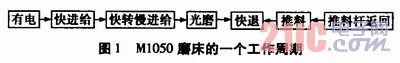
2.1 M-type grinder motor main circuit design M-type grinder frequency control main circuit wiring diagram, as shown in Figure 2. 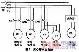
In the figure, QS is an air switch, and the hydraulic motor M2 and the guide wheel motor M5 can be started and stopped randomly. The grinding wheel motor M1 and the lubricating motor M3 are sequentially controlled. That is, the lubricating motor M3 is started first, and the grinding wheel motor is Start after M1. The guide wheel motor M5 is controlled by a frequency converter and has stepless speed regulation.
The inverter is set to external control mode 2 by Pr. The content of 79 can be written as 2. Stepless speed regulation is regulated by an external potentiometer on the inverter.