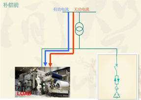
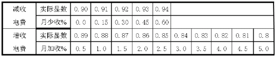
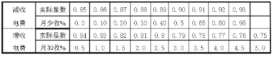
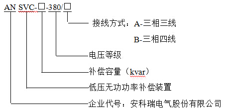
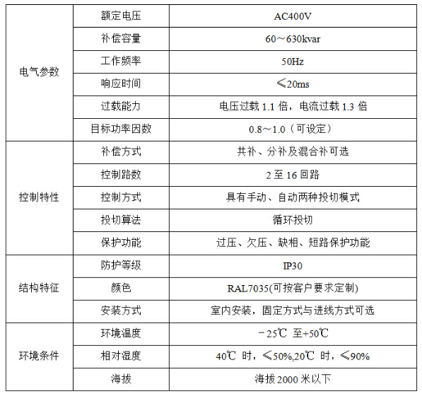
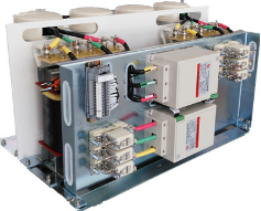
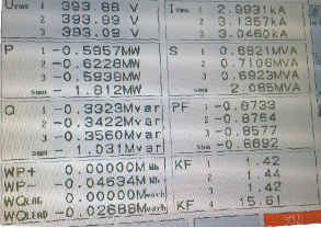
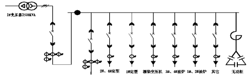
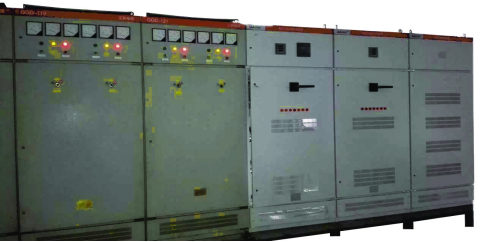
Ankerui Qingqing Jiangsu Ankerui Electric Appliance Manufacturing Co., Ltd. Jiangyin, Jiangsu 214405 Abstract: With the rapid development of China's economy, enterprises have put forward higher requirements for the demand for power supply and the quality of power equipment. The economical efficiency of power system operation is inseparable from the power quality and reactive power. The design of the power power compensation device is described and studied, and the application of the reactive power compensation device in the field is introduced. Keywords: power quality reactive power reactive power compensation design application Introduction: In recent years, with the rapid economic development, the concept of power quality management has received extensive attention among major companies. The concept of “electricity safety, power quality, and electricity economy†is firmly rooted in the people’s mind, and reactive power compensation is used as energy. The important part of quality management has also become the research direction of the majority of electric power people. The state has adopted an iron fist policy for enterprises that do not meet the target of reactive power, and the power rate has also become a burden on some power companies. In this paper, the design and selection of low-voltage reactive power compensation devices are described and analyzed. The operation and application of low-voltage reactive power devices in the field are illustrated by examples. 1 Active power and reactive power In an AC circuit, there are two kinds of electric power supplied from a power source to a load; one is active power and the other is reactive power. Active power is the electrical power required to maintain the normal operation of electrical equipment, that is, the electrical power that converts electrical energy into other forms of energy (mechanical, optical, thermal). Reactive power is relatively abstract. It is used for the exchange of electric and magnetic fields within a circuit and is used to establish and maintain the electric power of magnetic fields in electrical equipment. The relationship between apparent power, active power, and reactive power can be derived from the power triangle. The formula is as follows: For example, the motor needs to establish and maintain a rotating magnetic field, which causes the rotor to rotate, thereby driving the mechanical movement. The rotor magnetic field of the motor is established by obtaining reactive power from the power supply. The transformer also requires reactive power to generate a magnetic field in the primary coil of the transformer and induce a voltage in the secondary coil. Therefore, reactive power is not useless power and it occupies an important position in the power system. Without reactive power, the motor will not rotate, the transformer cannot be transformed, and the AC contactor will not pick up. 2 Introduction of Low Voltage Reactive Power Compensation Device The low-voltage reactive power compensation device plays a role in the power supply system to increase the power factor of the power grid, reduce the loss of the power transformer and the transmission line, improve the power supply efficiency, and improve the power supply environment. Therefore, the reactive power compensation device is in an indispensable position in the power supply system. Reasonable choice of low-voltage reactive power compensation device can minimize the loss of the network, so that users improve the quality of electricity. Conversely, unreasonable choices or improper methods of use may also cause uncontrollable factors such as voltage fluctuations, flicker, and harmonic amplification in the power supply system. 3 Principle of reactive power compensation device As can be seen from the power triangle, the user's transformer capacity (S) is fixed, if the user's equipment requires reactive power (Q) is too large, it will make the active power (P) output reduced. This will not only make the use of electrical equipment not work properly, it may also result in overload of the equipment and lead to equipment damage. In this case, reactive power compensation of the power system is required. As shown in Fig. 1, before the reactive power compensation is performed, the reactive power and active power of the load all come from the power grid through the transformer, which leads to a decrease in the power factor of the power grid, a drop in the power quality, and a poor power consumption efficiency. Fig. 2 compensates the reactive power of the equipment. At this time, the active power of the equipment comes from the power grid through the transformer, and the reactive power is taken from our reactive power compensation equipment. It is assumed that the reactive power of the equipment is extracted from the reactive power compensation equipment. At this time, from the grid side, the reactive power (Q) is 0, and the apparent power (S) at this time is equal to the active power (P). Is 1. At this time, the power supply efficiency of the power grid is the highest. Although this condition is ideal, in the actual operation, as long as the compensation is done properly, it is no problem that the monthly average power factor is above 0.95. Figure 1 Reactive compensation before the legend Figure 2 Reactive compensation after the legend 4 The importance of reactive compensation In general, the significance of using reactive power compensation devices to increase power factor is reflected in two aspects: First, it can reduce power loss on transmission lines; second, it can fully exploit the potential of power equipment (such as motors, transformers, etc.). Because electrical appliances always operate at a certain voltage and a certain active power, if the power factor is low, larger currents are needed to ensure normal operation of electrical appliances, and the transmission current becomes larger, leading to increased line losses. In addition, any electrical equipment always works within a certain rated voltage and rated current. If it exceeds the rated voltage, it will threaten the insulation performance of the equipment; if the operating current exceeds the rated value, the internal temperature rise will be too high, thus reducing the equipment. The service life. For some power generation equipment, the increase of power factor can greatly increase the efficiency, for example: a generator capacity of 1500kW, when the power system power factor increases from 0.6 to 0.8, the actual power generation capacity can be increased to 3000kW. 5 Economic Benefits of Reactive Compensation The economic benefits of reactive power compensation are mainly reflected in the rate of electricity, rate of electricity = active energy × electricity price × power rate adjustment factor. The power rate adjustment factor is obtained by looking up the table according to the power factor value. The benchmark tariff rate adjustment coefficients for different benchmarks are shown in Tables 1 and 2. Table 1 uses 0.90 as a standard worth rate adjustment schedule Table 2 uses 0.85 as a standard worth rate adjustment schedule The national standard has also been stipulated. Users who need transformers with capacities of 100 kVA and above and 10 kV should perform power factor assessment. The specific standards are as follows: For users under 100kVA and 160kVA (excluding 160kVA), the power factor must reach 0.85; The user power factor above 160kVA should reach above 0.90. The user's power factor is greater than the standard's reduction in its monthly electricity bill, and lower than the standard's increase in its monthly electricity bill. For example: a transformer user's transformer capacity of 160kVA, using low-voltage metering, a month to change the user's consumption of active power is 25000kWH, reactive power is 27000kWH, assuming the electricity fee is 0.68 yuan / degree. According to the research data, the transformer's active loss is 1036kWH, and the reactive loss is 3790kWH. So the user consumes 26,260kWH of active power and 30,790kWH of reactive power. Through the power triangle or lookup table, the power factor of the user is 0.65. . Through the lookup table, we can see that the user's power rate adjustment factor is +15%, a total of 25000×0.68 is actually charged for 17,000 yuan, and the required power rate is 25,000×0.68×0.15 is 2550 yuan, for a total of 19,550 yuan. . Now through the reactive power compensation for the user to increase the power factor from 0.65 to 0.95, through the lookup table shows that the user power rate adjustment factor is -0.75%, a total of 25000 × 0.68 to be charged for the actual consumption of electricity 17000 yuan, need to add The power rate for the power rate is 25000 x 0.68 x (-0.0075) -127.5 yuan, for a total of 1,6872.5 yuan. From the examples, we can see that the use of reactive compensation can generate great economic benefits for the company. Generally, equipment costs can be recovered within 10 months to a year, creating revenue for the company. 6 Reactive power compensation selection 6.1 Capacity Selection 6.1.1 New Project Because the on-site parameters cannot be determined for the newly-built project, in order to facilitate rapid selection, the industry is first categorized, and the industry-affiliated categories are shown in the following table ( I: coefficient II: coefficient III: Coefficient 6.1.2 Retrofit Project The reconstruction project generally needs to go to the site for on-site measurement, according to the actual situation of the site, configure the corresponding reactive power compensation program, the main points to be measured include: active power, reactive power, apparent power, actual power factor, target power factor, Load conditions, grid background, etc. The capacity of the reactive power compensation device can be calculated through actual measurement. For the above example, assume that the user transformer is fully loaded before compensation. The user's transformer capacity is 160kVA, the power factor is 0.65, and the target power factor is 0.95. as follows: The compensation front view power is The active power before compensation and after compensation does not change to Therefore, the reactive power that needs to be compensated is 6.2 Model Description 6.3 Technical parameters 7 Reactive power compensation modular solution At present, the low-voltage reactive power compensation devices on the market basically take the form of a complete cabinet. Basically, they all belong to the “one-stroke dealâ€. Although they can meet the user's on-site compensation requirements, they are very important in terms of maintenance and capacity expansion after compensation. The inconvenience, it is very difficult to replace the entire cabinet when the user needs to carry out the transformation. Figure 3 shows a reactive power compensation module that integrates a set of reactive power compensation circuits including capacitors, reactances, thyristor switching switches, fuses, and secondary circuits in one module. In actual use, the modules and modules are They are independent of each other and do not interfere with each other. In the course of maintenance and use, the modules can be increased or decreased in capacity and maintained. Fig. 3 Reactive power compensation module 8 Application Cases of ANSVC in Jiangsu Hongliu Sheet Co., Ltd. Project 8.1 Project Introduction Project Address: Jiangsu Hongliu Sheet Co., Ltd. The project address is located in Jiangyin City, Wuxi City, Jiangsu Province, which is beautiful and richly endowed. The project is located on the Yangtze River in the north, near the Taihu Lake in the south, Changshu, Zhangjiagang in the east and Changzhou in the west. It lies in the geometric center of the “Golden Triangle†in Suzhou, Wuxi and Changzhou. The transportation hub is convenient. . The average elevation of 6 meters, the temperature conditions throughout the year better, four distinct seasons. Jiangsu Hongliu Sheet Co., Ltd. covers an area of ​​150,000 square meters and a building area of ​​120,000 square meters. The project has purchased 2 sets of reactive power compensation cabinets and 1 active filter cabinet from our company. For reactive power compensation, the 1# transformer outlet side was measured. The measurement results are shown in Figure 4 and the target power factor is 0.98. The on-site power distribution system harmonic sources are mainly frequency converters and switching power supplies. Harmonic frequencies are 3, 5, and 7 The second and eleventh times are typical 6n±1 characteristic harmonics, which are controlled by the ANAPF active filter to protect the capacitors. The measurement is schematically shown in Figure 5: (black circles are measurement points). Fig. 4 Reactive power compensation field measurement results Figure 5 on-site measurement 8.2 Reactive Power Compensation Capacity Calculation The compensation front view power is The active power before compensation and after compensation does not change to Therefore, the reactive power that needs to be compensated is Considering the difference between the actual compensation capacity and the nominal compensation capacity, considering the fact that only 800mm depth cabinets can be placed in the field, a 350kvar main cabinet and a 350kvar auxiliary cabinet are selected for a total of 700kvar. 8.3 Field Usage Figure 5 site installation diagram Figure 6 site completion 9 Conclusion This paper describes the design and selection of low-voltage reactive power compensation devices from the aspects of basic knowledge, selection parameters, economic benefits, and example design of low-voltage reactive power compensation devices. A new idea of ​​modular low-voltage reactive power compensation device was proposed. The rational allocation of low-voltage reactive power compensation devices can not only reduce line losses, improve equipment life and operating efficiency, but also can reduce the rate of fines for enterprises, obtain electricity rewards, and intuitively create economic benefits. ã€references】 [1] GB15576-2008-T Low Voltage Complete Reactive Power Compensation Device [2] Ancorui Electric Co., Ltd. Product Manual, 2013.01.
EvoTec special generators mainly include 4 Pole ,Evotec Special Generator,4 Pole Alternator, Ip22 Generator ,Explosion-Proof Generator, high-efficiency special type generator (350kVA efficiency up to 96%), Ip55 Generator (delivered more than 20 units to European Countries ), and medium-speed generator , Generator with auxiliary winding ,which are widely used in industrial fields such as mining, metallurgy, oil fields, etc.
EvoTec has several senior experts in the field of generators, as well as large-scale owned factory. with strong independent research and development capabilities, EvoTec builds customized alternators adapted to specific power plant applications.
Low losses magnetic steel
reinforced construction for high linear vibrations
flanged shaft for direct coupling with engine flywheel (in case of single bearing solution)
neutral point terminals in separate terminal box
increase protection degree up to IP 54, IP 55
insulated bearing and back shield
digital AVR
excitation PMG mounted on generator
lubrication system for sleeve bearing
other options available on request
EvoTec Special Generator 4 Pole,Evotec Special Generator,4 Pole Alternator,Ip22 Generator EvoTec Power Generation Co., Ltd , https://www.evotecgen.com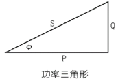


 ,
,  Refers to the reactive compensation capacity,
  Refers to transformer capacity,
  Refers to the coefficient of reactive compensation industry):
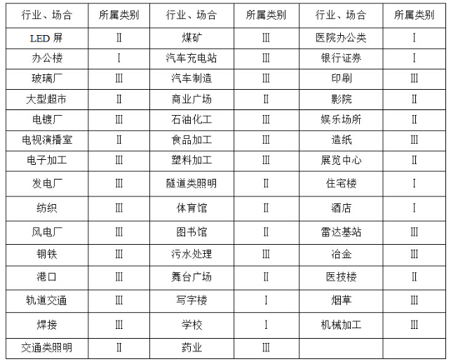
 About 0.3, suitable for offices, residential and other harmonics, reactive power demand is relatively small occasions;
  About 0.4, suitable for commercial, rail transit and other harmonics, reactive power demand is relatively moderate occasions;
  About 0.55, suitable for heavy industries, manufacturing and other harmonics, relatively large demand for reactive power;
  , power factor
  The active power before compensation is
  , Reactive power before compensation is
  .
.  , target power factor
  The compensated rear view power is
  The compensated reactive power is
  .
.  .
. 
 , power factor
  The active power before compensation is
  , Reactive power before compensation is
  .
.  , target power factor
  The compensated rear view power is
  The compensated reactive power is
  .
.  .
. 
Some features for EvoTec Special Generator :
EvoTec Special Generator
