1. introduction With the rapid development of the semiconductor industry, semiconductor devices gradually replace most of the electronic tube devices because of their advantages of small size, low energy consumption, and stable performance. However, in modern radio engineering systems, high-power, ultra-high frequency electronic devices still occupy Irreplaceable status. In radio and radar transmission systems, high-power high-frequency electron emission tubes such as magnetrons, klystrons, traveling wave tubes, and EBS tubes are indispensable core devices. In this type of device, the most important component is the electron beam. Its main function is to convert the power energy into high-frequency oscillation energy during the interaction with the electromagnetic field. The quality of a launch system depends primarily on the performance of the electron-emitting tube, and the radio-frequency performance, frequency agility, heat dissipation, power, gain, and efficiency of the electron-emitting tube all depend on the performance of the electron beam. Therefore, the structure and parameters of the electron beam are studied. The cross section size, current density distribution, pulsation, electron trajectory, and electron trajectory of the electron beam are analyzed. It is important to improve the performance of the electron emission tube. significance. The electronic injection analysis system is designed and developed according to the above requirements. The system can conduct experimental research on the structure and performance of the electronic injection, and can complete the comprehensive measurement of various parameters of the electronic injection. 2. Electronic injection analysis system working principle The principle of electron injection analysis system is shown in Figure 1. The system is mainly composed of the electron gun to be tested, the collector, XYZ three-coordinate precision moving table, current amplifier, A/D converter, and computer data acquisition system and information processing system. The electron gun to be tested is an electron injection and emission system consisting of a filament, a cathode, a modulation anode (or control grid), and a focusing electrode. The electron gun emits a beam of electrons through the cathode, modulates the modulation of the anode (or control grid), and then passes through the focusing pole. Electron beam formation. The collector and XYZ three-axis precision moving tables are the most critical components in the electron injection analysis system. In order to accurately analyze the characteristics of the electron injection structure and each parameter, it is necessary to measure the current, current density distribution, cross-sectional area size, and distribution regularity along the axial direction of the electron injection total beam current, electron injection at each point on different sections. To meet the measurement requirements, we designed inlet diameters as Fig.1 Working principle diagram of electron annotation analysis system 3. Design of Three-axis Precision Mobile Workbench The three-axis precision moving table is the core part of the entire electron injection analysis system, and it is also the most difficult part of the design. When measuring the size of electron injection cross-sectional area, current density distribution and electron injection along the axial characteristic distribution, the technical parameters, such as the spacing retention, sampling uniformity, and the positioning accuracy of the collector in the space, of the collector's point-by-point sampling within the three-dimensional space are completely It depends on the performance of the three-axis precision moving table. In addition, the degree of vacuum has a great influence on the performance of electron injection. When the vacuum level is lower than 1.33×10⁻³Pa, severe ion accumulation and neutralization of ions and electrons will occur near the electron beam axis, resulting in the cathode center of the electron gun. The occurrence of ion spots, the existence of ion spots will make the electron beam show a significant non-laminarity and strong divergence, so that the current density distribution and lateral velocity distribution in the electron injection significantly change, the anode capture electrons increase, which greatly affect Device performance. Therefore, in the electron injection analysis system, the electron gun, the collector, and the three-coordinate precise moving table must work in an environment with a vacuum degree of 1.33×10⁻⁵ Pa. This requires the three-coordinate precision moving table to ensure the measurement range. On the premise of motion accuracy and work stability, it must be rationally laid out, compact in structure, and minimized in size, which adds difficulty to the design. The technical specifications of the three-axis precision moving table are as follows: Figure 2 Structure of a three-coordinate precision moving table Since the collector is required to be placed on the moving part of the table and the stroke in the Z coordinate direction is taken into account, in order to reduce the center of gravity of the entire table system and reduce the bending stress of the Z coordinate guide, we will use the Z coordinate when designing the table structure. The shaft is placed on the top layer, the transmission method adopts the screw and nut mechanism, and the guide device adopts two sets of linear motion ball bearings and two precision guide rods. The guide rod and the lead screw are connected to the work table through ball bearings and nuts to support the work table, so that the work table is evenly distributed, flexible, and stable in motion, so as to ensure the motion accuracy in the Z coordinate direction. The Y-axis guides are placed on the middle floor, and the X-axis guides are placed on the lowermost floor. The Z-axis guides are placed on the moving parts of the Y-axis guides, and the Y-axis guides are placed on the moving parts of the X-axis guides. The drive system of X and Y axis guide rails adopts screw and nut mechanism. Taking into account the X, Y-axis rail travel is small, but the movement sensitivity and positioning accuracy requirements are higher, at a low speed does not allow crawling, so design X, Y-axis rail ball guide selected to ensure that the guide rail movement accuracy and smooth movement Sex. 4. Computer System and Three-axis Precision Mobile Workbench Control The main functions of the computer system of the electronic note analysis system are: (1) to complete the control of various parameters of the electron injection emission system, and the data collection of the collector and the electron injection analysis system; analysis of the magnetic field, anode current, and electron injection system The relationship between load conductance, load susceptance, output power, and other parameters is plotted, and the operating characteristic curve of the electron injection emission system is plotted. (2) Complete the drive and control of the three-axis moving table to realize the motion control and electron beam sampling at any position in the three-dimensional space. FIG. 3 is a schematic diagram of a computer system and a three-axis moving table driving system. The entire system consists of a computer, an 8751 microcontroller, and an electronic injection analysis system software. The computer completes the control and collection signal acquisition, analysis and processing of the electron injection emission system; the single-chip microcomputer system is connected with the computer through the serial communication port, and the computer sends a command pulse to the one-chip computer system according to the program given by the electronic injection analysis system software. The processing circuit and the drive circuit complete the control of the X, Y, Z three-axis stepper motor. In order to be able to input and update given values, modify the parameters in the control program, we use a programmable keyboard display interface chip 8279 to automatically complete the keyboard scan input and LED scan display. The operating characteristics of the electron beam injection system and the processing results of the electron beam analysis system are output by the CRT display and the printer. Fig. 3 Schematic diagram of computer system and three-axis moving table driving system 5. Conclusion The electronic injection analysis system uses a three-coordinate precision moving table to drive the collector to sample the beam of electrons injected at any position in the three-dimensional space, and then processed by the computer system to realize the comprehensive measurement of structural parameters and working performance of the electron injection and emission system. analysis. Compared with the fluorescence measurement method commonly used in the country, this method has greatly improved the degree of automation, measurement reliability, and measurement accuracy, and will play an important role in the development of ultra high frequency high power electronic devices.
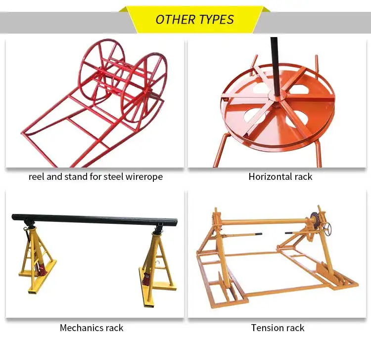
Ordinary Type Hydraulic Cable Reel Stand
Cable reel stand is used to lift, support and stabilise low and high voltage cable drums to enable efficient cable laying and pulling for low and high voltage cables.
It is applicable to the placement of the cable tray,hydraulic lifting,carrying the weight of a large.
Product Details:
The bottom with small wheels,easy to move,can be equipped with a braking device,using the foot brake.
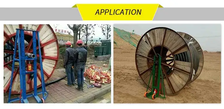
Application:
Cable Reel Stand applied in the supporting of cable drum. With trapezoidal structure, it can be applied in different kinds of reel specification. Hydraulic lifting make it lift easily, trundles installed on the bottom make it easy to move, simple operation, secure and durable.
Cable Reel Stand Cable Reel Stand,Cable Reel Holder,Wire Reel Stands,Electrical Cable Reel Stands Hebei Long Zhuo Trade Co., Ltd. , https://www.hblongzhuo.com![]() 0.1mm and
0.1mm and ![]() 20mm two Faraday cups as collectors. The use of a large-gauge collector to measure the total beam current of the electron beam enables the electron beam to be fully loaded into the collector to prevent electrons from escaping from the entrance. The use of a small-gauge collector to measure the current density distribution of the electron beam enables the electron beam cross section to be sampled. Increased to improve measurement accuracy. In the structure design of the collector, it should be considered that the secondary electrons are generated and the escape of the reflected electrons is prevented by the electron beam striking the surface after the electron beam enters the inside thereof. The movement of the collector in the three coordinate directions of the three-dimensional space is performed by the XYZ three-coordinate precision movement table. The computer system issues instructions according to the measurement requirements. The stepper motor drives the precision moving table coordinate axis to drive the collector to move in the three-dimensional space and obtain sampling information. Collector output electrons flow through current amplification and A/D conversion to the computer. The computer system analyzes and processes the sampled data, obtains electronic injection parameters and work characteristics, and prints data, tables, and curves.
20mm two Faraday cups as collectors. The use of a large-gauge collector to measure the total beam current of the electron beam enables the electron beam to be fully loaded into the collector to prevent electrons from escaping from the entrance. The use of a small-gauge collector to measure the current density distribution of the electron beam enables the electron beam cross section to be sampled. Increased to improve measurement accuracy. In the structure design of the collector, it should be considered that the secondary electrons are generated and the escape of the reflected electrons is prevented by the electron beam striking the surface after the electron beam enters the inside thereof. The movement of the collector in the three coordinate directions of the three-dimensional space is performed by the XYZ three-coordinate precision movement table. The computer system issues instructions according to the measurement requirements. The stepper motor drives the precision moving table coordinate axis to drive the collector to move in the three-dimensional space and obtain sampling information. Collector output electrons flow through current amplification and A/D conversion to the computer. The computer system analyzes and processes the sampled data, obtains electronic injection parameters and work characteristics, and prints data, tables, and curves. 
X coordinate direction stroke: 0 ~ 30mm; adjacent measurement point sampling interval: 0.05mm; error: 0.005mm.
Y coordinate direction stroke: 0 ~ 30mm; adjacent measurement point sampling interval: 0.05mm; error: 0.005mm.
Z coordinate direction stroke: 0 ~ 30mm; adjacent measurement point sampling interval: 0.05mm; error: 0.005mm.
The coordinate axes X, Y and Z of the three-axis precision moving table are respectively driven by stepping motors, and the collector is installed on the workbench. The stepping motor is controlled by a computer system and drives each coordinate axis to drive a worktable equipped with a collector to perform point-by-point sampling in the three-dimensional space of the electronic injection measurement system according to a certain sequence and corresponding steps. The structure of a three-coordinate precision moving table is shown in FIG. 


