First, the tank voltage Wherein V groove - groove voltage; That is, electrical energy efficiency (η e ) = current efficiency (η i ) × voltage efficiency (η V ) Where I - the current through the electrolytic cell, A;
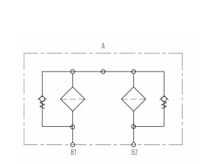
SDRFD filter consists of one-piece housings with a bolt-on cover plates. The two housings are connected by a ball change-over valve. There are clogging indicators on both sides.
Symbol for hydraulic systems
Filter elements are available with the following pressure stability values:
BN/HC: 25 bar
Paper(P/HC): 10 bar
Wire mesh( W/HC ): 30 bar
Stainless steel fiber( V ): 30 bar
Compatibility
It can be used for mineral oils, lubrication oils, non-flame fluids, synthetic and rapidly biodegradable fluids. For water or other application, please contact us.
General
Mounting
Tank-top mounted or inline filter.
Flow
Inlet: by a ball change-over valve
Outlet: down
Temperature range
-10℃~100℃(others on request)
Pressure setting of clogging indicator
â–³Pa=2bar-0.2bar (others on request)
Bypass cracking pressure
â–³Po=3bar-0.5bar (others on request)
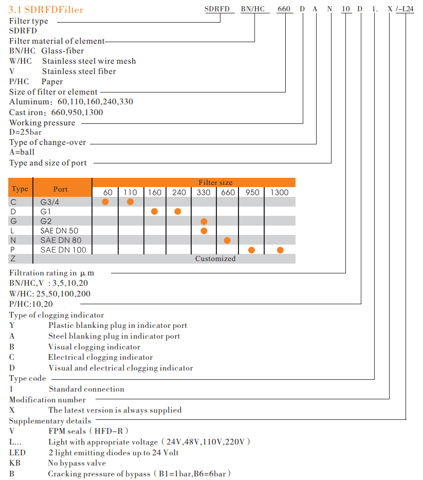
Model code
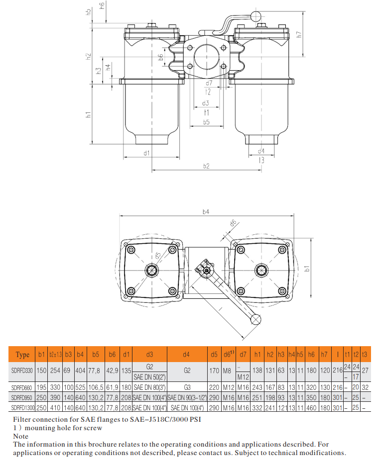
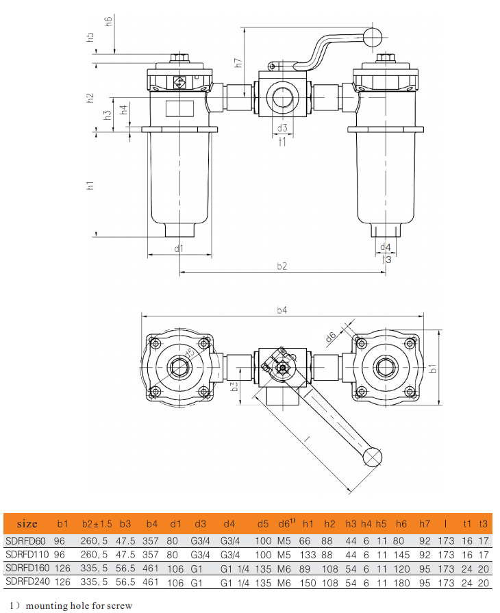
Filter Dimension
Excavator Filter,Double Housing Filter,Housing Filter,Filter Housing Xinxiang Shengda Filtration Technique Co., Ltd. , https://www.filtrations.nl
The tank voltage is the low voltage between adjacent anodes and anodes in the cell. It can be expressed by the actual voltage between each pair of cathode and anode. However, in the production practice, because the number of electrolytic cells is large, the number of anodes and cathodes is more, and the voltage drop between each pair of anodes and cathodes varies depending on the specific conditions, so the measurement method is not used, but The voltage drop of the total voltage-reduced conductive plate supplied to all series of electro-stacks is divided by the total number of slots on the series circuit, and the resulting high is the cell voltage, which is expressed as 
V 1 - the total voltage of all electrolytic cells connected in series;
V 2 - the voltage drop of the conductive plate;
N - the total number of electrolytic cells.
The voltage of an electrolytic cell consists of the theoretical decomposition voltage of electrolytic MnO 2 , the voltage drop of the electrolyte solution, and the voltage drop caused by the contact resistance of the wiring, the resistance of the plate, etc., expressed as V- groove = (φ + -φ - ) + IR liquid + IR pole + IR connection
Where (φ + -φ - ) - the polarization potential of the electrode, ie the theoretical decomposition voltage of the electrolytic MnO 2 ;
IR liquid - electric effluent resistance voltage drop;
IR pole - plate resistance voltage drop;
IR connection - contact resistance voltage drop.
Although ion-conducting electrolyte can rely on, but compared with the metal conductor, overcast much greater. When the current passes through the electrolyte, it will inevitably cause a pressure drop. Its magnitude is proportional to the current density, the distance between the yin and yang, and the resistivity of the electrolyte. It can be expressed by the following formula: V liquid = IR liquid = J · ÏL
Where V liquid - electrolyte resistance voltage drop, V;
J——anode current density, A/m 2 ;
Ρ——resistance of electrolyte, Ω · m;
L——Yin and anode Liu distance, m.
It should be pointed out that industrial production inevitably has other ions (such as Mg 2+ , Ca 2+ , etc.), so the actual electrolyte voltage drop is larger than the above calculated value, generally between 0.4 and 0.6V. In order to reduce the power consumption, it is desirable to reduce the value of the V liquid . This requires lowering the current density and shortening the distance between the poles, but at the same time it is disadvantageous for improving current efficiency and strengthening production. Therefore, the electrolysis conditions must be reasonably determined.
Titanium anode plates and conductive heads have a certain resistance, which consumes a part of the voltage, generally around 0.2V. Or a copper cathode carbon rod and the conductive plate systems also have a certain resistance, also consumes a portion of a voltage of about 0.02V.
The cathode-anode contact tip also has a contact voltage drop at the contact point, which is about 0.03V. Since such contact electrical connectors are tens of thousands in industrial production, efforts to reduce the voltage drop at the contact point have important practical significance for saving electrical energy. In actual operation, it must be noted that each contact point conducts well.
The sum of the above four resistance voltage drops is the tank voltage of the electric forest. The cell voltage is also determined by the current density, the acidity and temperature of the electrolyte, and the distance between the electrodes, in addition to the contact resistance. Therefore, the way to reduce the cell voltage is to reduce the resistivity of the electrolyte, shorten the distance between the electrodes, and reduce the voltage loss at the contact point.
According to the test data of Mei Guanggui et al., the titanium material is used as the anode and the carbon rod is used as the cathode. The cell voltage of the electrolytic MnO 2 is generally 2.5~3.0V, and the purple Cu tube is used as the cathode, generally reducing the cell pressure by about 0.5V. The Ti-Mn alloy coating is used as the anode, and the anode sun is passivated to reduce the cell voltage by about 0.2V. [next]
Second, electrical energy efficiency
Electrical energy efficiency is the ratio of the amount of metal that is theoretically necessary to the amount of electricity actually produced in an electrolytic production process. 
In order to improve the efficiency of electric energy, in addition to improving the current efficiency, do not increase the voltage efficiency. The way is to reduce the electrolyte resistance, appropriately increase the temperature of the electrolyte, shorten the pole pitch to reduce the polarization of the electrode, and reduce the voltage of the tank.
Third, power consumption
Electrical energy efficiency represents the technical level of the electrowinning process. However, in production practice, it is rarely calculated as a regular indicator. In the factory practice, as the actual electric energy consumption that is often calculated, that is, the electric energy (kw · ht) consumed per ton of MnO 2 produced, expressed in W, the calculation formula is 
T——the time of electrolytic deposition, h;
N——the number of electrolytic cells;
q——Electrification equivalent of MnO 2 , 1.6216gA -1 · h - ;
V- groove - slot voltage, V;
η i - current efficiency, %;
W——Preparation of electricity consumption per ton of MnO 2 , kW · h.
According to industrial production data, the direct current consumption of electrolytic MnO 2 is generally 2000~2500kW · h/t.


