Stainless Steel Mixer,High Speed Mixer Machine,Swing Drum Blender Jiang Yin Jun Lang Machinery Co.,Ltd , https://www.fluidbeddry.com
Control valves play a critical role in monitoring and managing key process parameters such as fluid flow and pressure. These valves rely on a component known as the positioner to execute their functions effectively. While a controller can manage the basic open/close operations of a control valve, confirming its exact position requires a positioner. Ensuring the precision of a control valve's operation depends heavily on the accuracy of its position, which is regulated by the positioner. Through a feedback mechanism, the positioner monitors the valve's position. Calibrating the control valve positioner is an essential task that must be carried out accurately to achieve the desired outcomes. If you're unsure about how to calibrate a positioner, this article walks you through the vital steps involved in the calibration process.
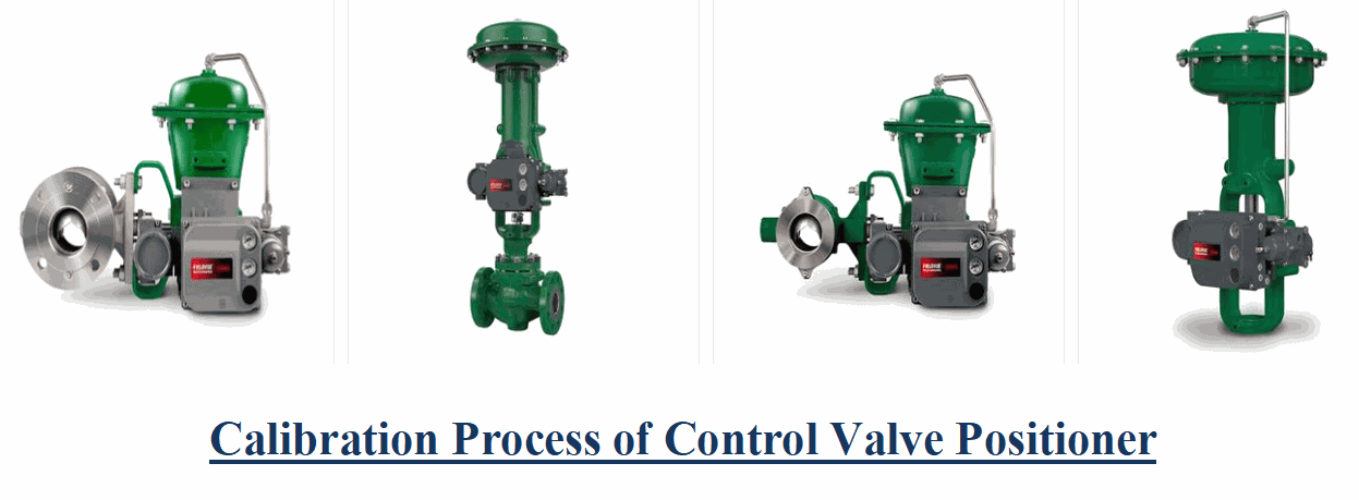
### Construction of a Positioner Assembly
To understand the calibration process better, it’s important to grasp the design of a positioner assembly. Here are some key points:
- A control valve’s positioner assembly includes components such as a flapper-nozzle, cam linkage, summing beam, and spring, all interconnected through mechanical linkages.
- The summing beam connects the cam-spring linkage to the bellow.
- The cam-spring's actions are guided by the pressure applied by the flapper-nozzle, which ultimately drives the movement of the summing beam.
- The diaphragm indicates the pressure being applied or exerted by the flapper assembly.
### Overview of Step-by-Step Calibration of Control Valve Positioner
The positioner controls the flapper's movement, with the summing beam moving in reverse or forward directions, acting as a feedback mechanism to the positioner. Given the closed-loop nature of the positioner and feedback mechanisms, the calibration process involves two main parts: zero adjustments and span adjustments. Let’s delve into the steps involved.
### Zero Adjustments:
Zero adjustments are made by fine-tuning the nozzle pin. Here’s how:
- Observe the measurable pressure range on the supply gauge and move the flapper assembly to the mid-level of the force beam on the forward movement side.
- Set the input value to the lowest reading.
- Gradually adjust the nozzle pin until you reach a zero value.
- Slowly increase the input pressure to 3 psi and confirm whether the output reads zero. If it does, the zero adjustment is precise.
### Span Adjustments:
Span adjustments involve positioning the flapper assembly at a particular level. The following steps outline the process:
- Increase the input pressure gradually until it reaches the maximum pressure value, typically 15 psi.
- At 15 psi input, verify that the output achieves the maximum of 20 psi.
- To adjust the span, manipulate the flapper assembly by shifting the force beam. Ensure that zero adjustments have been made to keep the force beam at the mid-level.
- If the saturated output value falls within the minimum measurable range, move the flapper assembly to a lower setting. Conversely, if the output is saturated at the maximum measurable range, shift the flapper assembly to a higher position.
This concludes the calibration process for the positioner of a control valve. However, precision is key during calibration, making it essential to perform this task under expert supervision. Therefore, consider partnering with skilled calibration services such as **The Transmitter Shop**. This company provides reliable calibration and maintenance services. Additionally, you can purchase high-quality control valves from trusted suppliers to ensure their functionality and reliability.
### Related Posts
- Causes & Solutions of Annoying Noise from Control Valves
- Understanding Industrial Control Valves and Their Types
- All Important Questions on Control Valves Answered
- 3 Common Control Valve Maintenance Practices
- Know Everything About the Benefits, Applications, Types, and Automation of Control Valves
- How to Select the Right Control Valve for Your Process?
- Calibration of Control Valve Positioner: The Process Discussed
- Control Valve Actuators: Different Types and Failure Modes Discussed
- Calibration Guide for Fisher 3582 Pneumatic Positioner
- How to Perform Periodic Inspections and Maintenance of Control Valves?
- Temperature Control Valve – Definition and Working Principle
- Reasons to Choose Remanufactured Instrumentation and Control Valves
- Fluid Flow Isolation Techniques for Pressure Instrumentation
- Single Acting vs. Double Acting Positioners: Pros and Cons
By understanding the calibration process and the importance of precision, you can optimize the performance of your control valves and ensure smooth operations in your processes.